Seebeck Effect
Tags
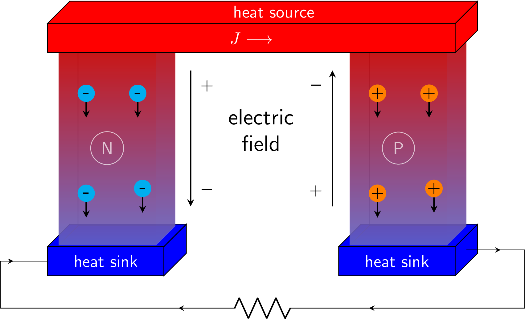
The Seebeck effect creates a voltage in conductors or semiconductor when subjected to a temperature gradient, i.e. when one side of the material is warmer than another. This effect enables thermoelectric devices which can measure temperature and generate electricity from waste heat.
Edit
Download
Code
seebeck-effect.tex (76 lines)
\documentclass{standalone}

\usepackage{circuitikz}
\usetikzlibrary{3d,positioning,decorations.markings}

\tikzset{
decoration={%
  markings,%
  mark=at position 0.05 with {\arrow[black]{stealth};},%
  mark=at position 0.4 with {\arrow[black]{stealth};},%
  mark=at position 0.6 with {\arrow[black]{stealth};},%
  mark=at position 0.95 with {\arrow[black]{stealth};}},
gradient/.style ={bottom color=blue!50, top color=red},
pics/.cd,
  p charge/.style={code={
      \node [fill=orange, shape=circle, inner sep=0pt] (pc) {+};
      \draw[thick,->] (pc)--++(0,-0.5);
  }},
  n charge/.style={code={
      \node [fill=cyan, shape=circle, inner sep=1pt, scale=1.2] (nc) {-};
      \draw[thick,->] (nc)--++(0,-0.5);
  }},
}

\newcommand\heatsink{
  \draw[fill=blue] (0,0,0) rectangle ++(6,1.5,0)node[midway,color=white]{heat sink};
  \draw[fill=blue] (6,0,0) -- ++(0,1.5,0) -- ++(0,0,-3) -- ++(0,-1.5,0) -- cycle;
  \draw[fill=blue] (0,1.5,0) -- ++(6,0,0) -- ++(0,0,-3) -- ++(-6,0,0) -- cycle;

  \draw[gradient,opacity=0.5] (0.5,1.5,-2.8) -- ++(0,10,0);
  \draw[gradient,opacity=0.5] (0.5,1.5,-2.8) -- ++(5,0,0);
}

\begin{document}
\begin{circuitikz}[scale=0.4,font=\sffamily,>=stealth]

  \begin{scope}
    % heat sink 1
    \heatsink
    \draw[gradient,opacity=0.5] (0.5,1.5,-2.8) -- ++(0,0,2.6);
    \fill[gradient,opacity=0.7] (5.5,1.5,-0.2) -- ++(0,10,0) -- ++(0,0,-2.6) -- ++(0,-10,0) -- cycle;
    \fill[gradient,opacity=0.7] (0.5,1.5,-0.2) rectangle ++(5,10,0)node[midway,draw,circle,white] (N) {N};
    \pic[below left=8mm and 3mm] at (N) {n charge};
    \pic[below right=7mm and 6mm] at (N) {n charge};
    \pic[above left=1cm and 3mm] at (N) {n charge};
    \pic[above right=1cm and 5mm] at (N) {n charge};
  \end{scope}

  \begin{scope}[xshift=15cm]
    % heat sink 2
    \heatsink
    \draw[gradient,opacity=0.5] (0.5,1.5,-2.8) -- ++(0,0,2.6);
    \fill[gradient,opacity=0.7] (5.5,1.5,-0.2) -- ++(0,10,0) -- ++(0,0,-2.6) -- ++(0,-10,0) -- cycle;
    \fill[gradient,opacity=0.7] (0.5,1.5,-0.2) rectangle ++(5,10,0)node[midway,draw,circle,white] (P) {P};
    \pic[below left=8mm and 3mm] at (P) {p charge};
    \pic[below right=7mm and 6mm] at (P) {p charge};
    \pic[above left=1cm and 3mm] at (P) {p charge};
    \pic[above right=1cm and 5mm] at (P) {p charge};
  \end{scope}

  % heat source
  \draw[fill=red] (0,11.5,0) rectangle ++(21,1.5,0) node[midway,white] (J) {$J\longrightarrow$};
  \draw[fill=red] (21,11.5,0) -- ++(0,1.5,0) -- ++(0,0,-3) -- ++(0,-1.5,0) -- cycle;
  \draw[fill=red] (0,13,0) -- ++(21,0,0) node[color=white,above right=0 and -5mm,pos=0.5]{heat source} -- ++(0,0,-3) -- ++(-21,0,0) -- cycle;

  % electric field
  \node[below=1cm,scale=1.3,align=center] at (11,11.5) {electric\\field};
  \draw[thick,-stealth] (6.8,10,-1.5) node[below right=1mm]{+} -- ++(0,-7,0)node[above right=1mm,scale=1.2]{--};
  \draw[thick,-stealth] (14.1,3,-1.5) node[above left=1mm]{+} -- ++(0,7,0)node[below left=1mm,scale=1.2]{--};

  % resistor
  \draw[postaction={decorate}] (21,0.75,-1.5) -- ++ (3,0,0) -- ++(0,-3,0) to[R] ++ (-27,0,0) |- (0,0.75,0);

\end{circuitikz}
\end{document}